LIGHT PIPE FOR ILLUMINATING THE INTERIOR OF A
PRESSURE VESSEL
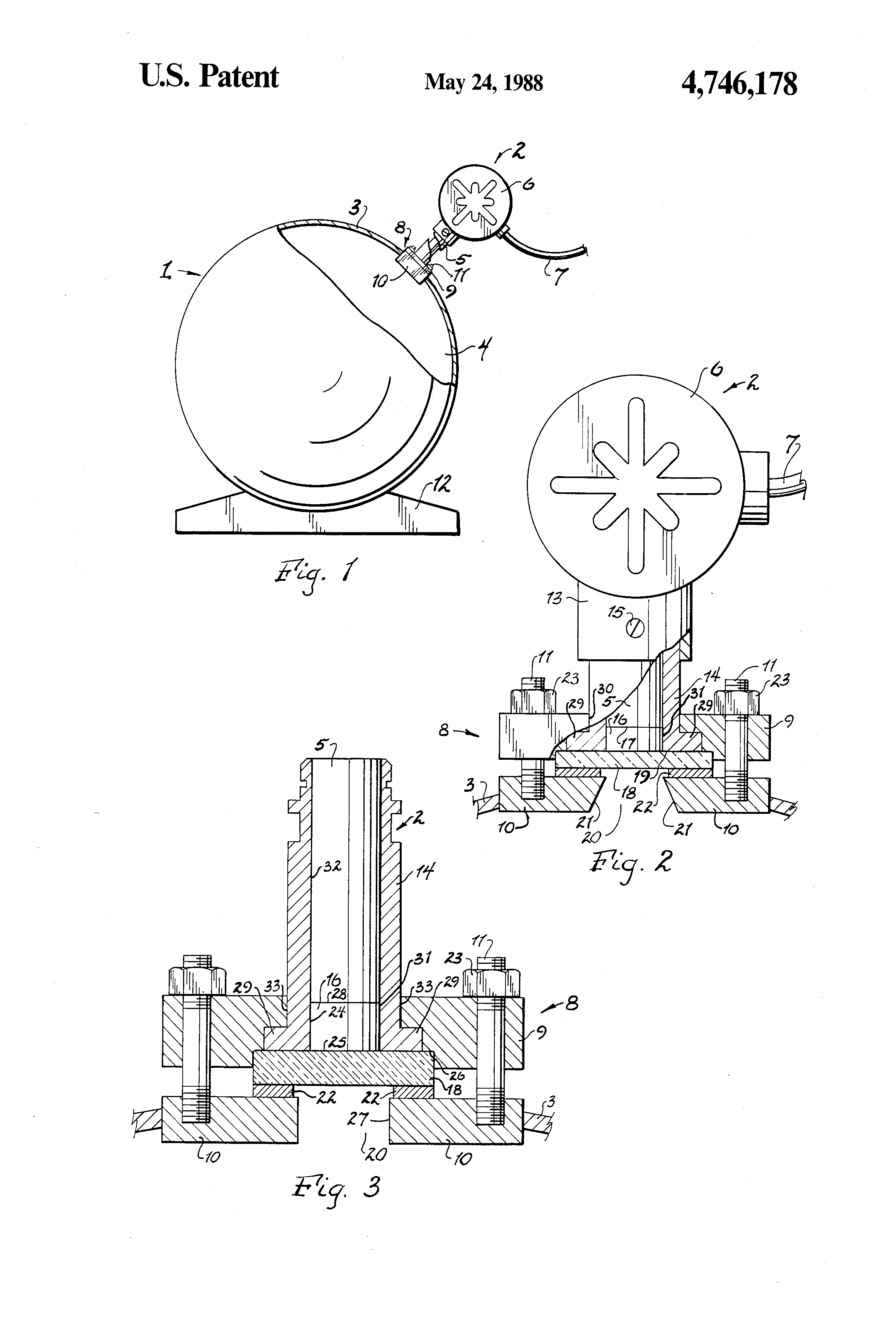
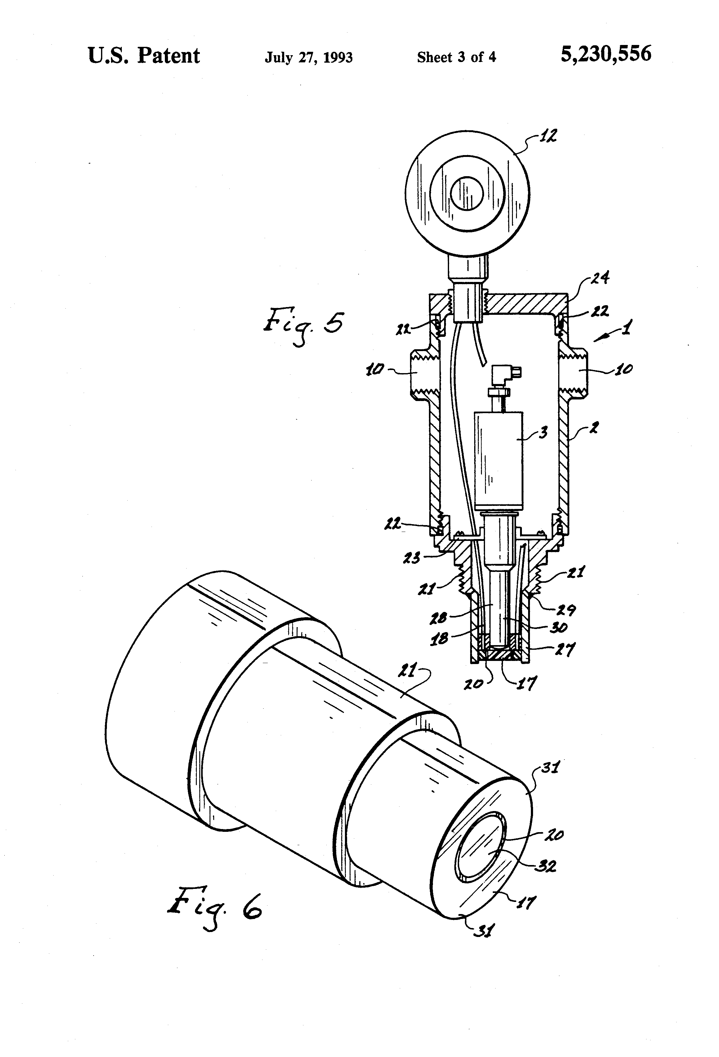
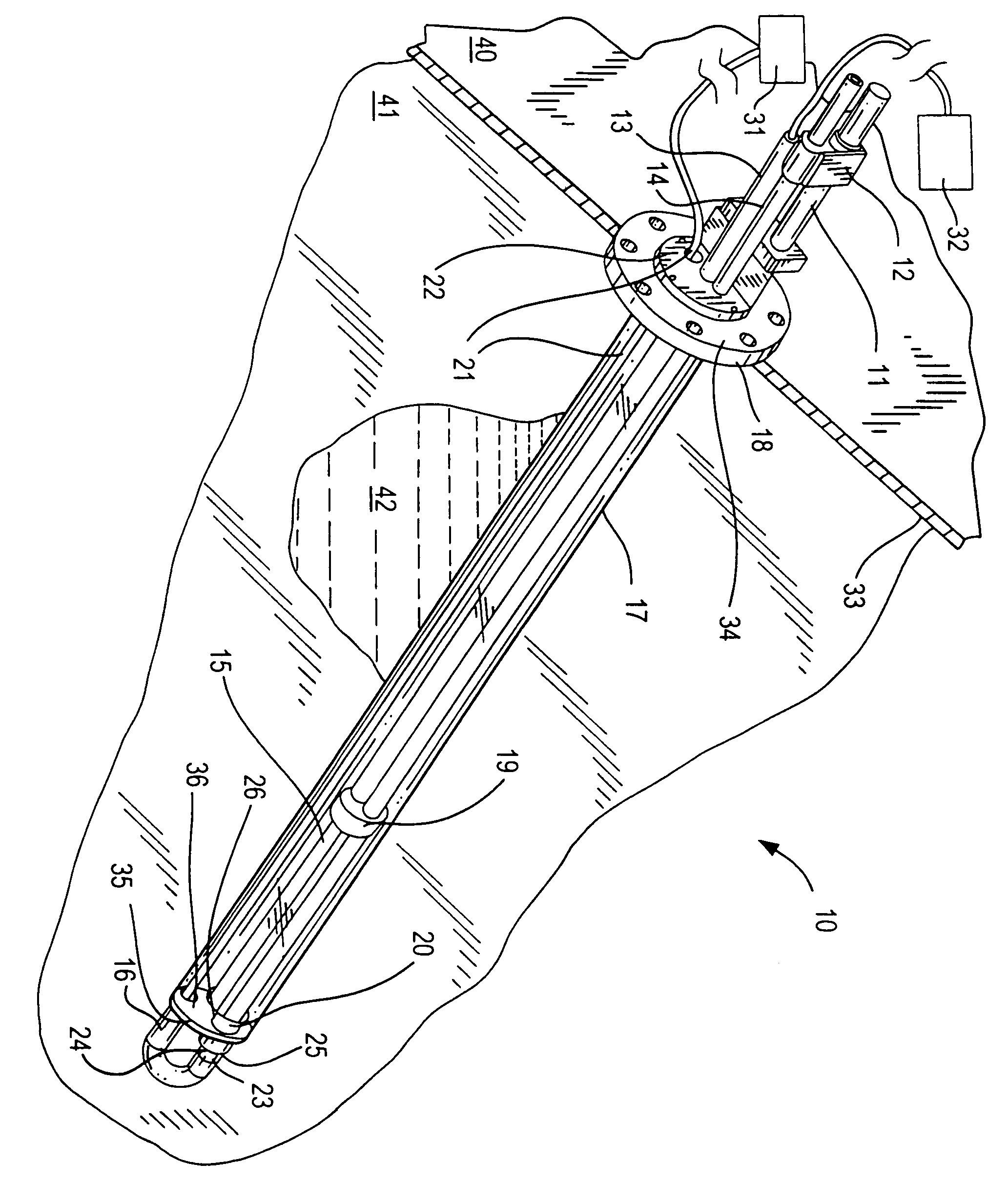
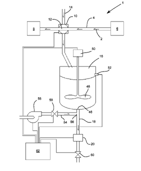
A light pipe unit for supplying illumination to the interior of a vessel that has an attachment means for connection to the vessel. The light pipe unit is constructed of a metallic housing having an elongated fiber optic rod contained therein. At the bottom portions of the rod and housing, that is the portions extending into the vessel, is a glass laminate. The glass laminate covering forms a substantially corrosion-proof seal across the entire distal or lower portion of the unit.
FUSEVIEW LAMINATE
SAFETY
SIGHT GLASS
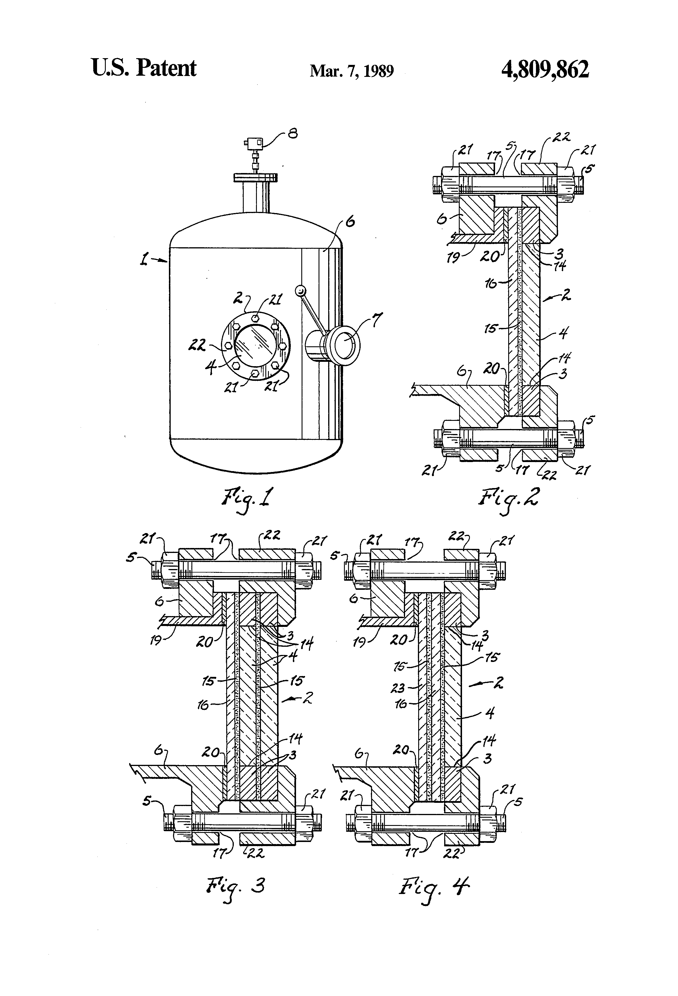
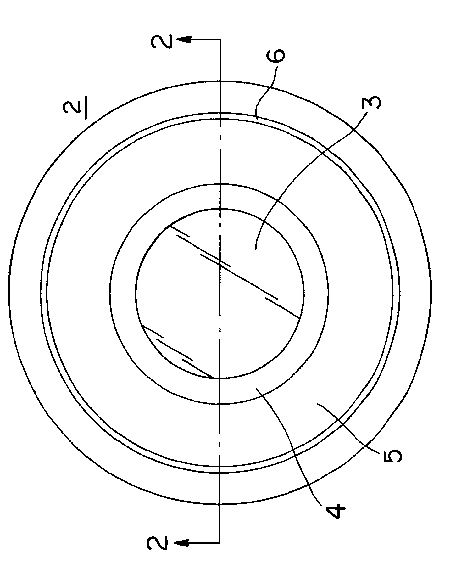
A safety viewing window for observing the interior of a pressure vessel is the subject of this invention. This viewing window is made up of an optically clear window disc fused to a metal frame. A laminate is overcoated over the fused disc and frame to provide a corrosion resistant viewing window. The metal frame has attached to it brackets for securing the entire unit to the vessel in a pressure tight manner.
HIGH PRESSURE / TEMPERATURE
CAMERA
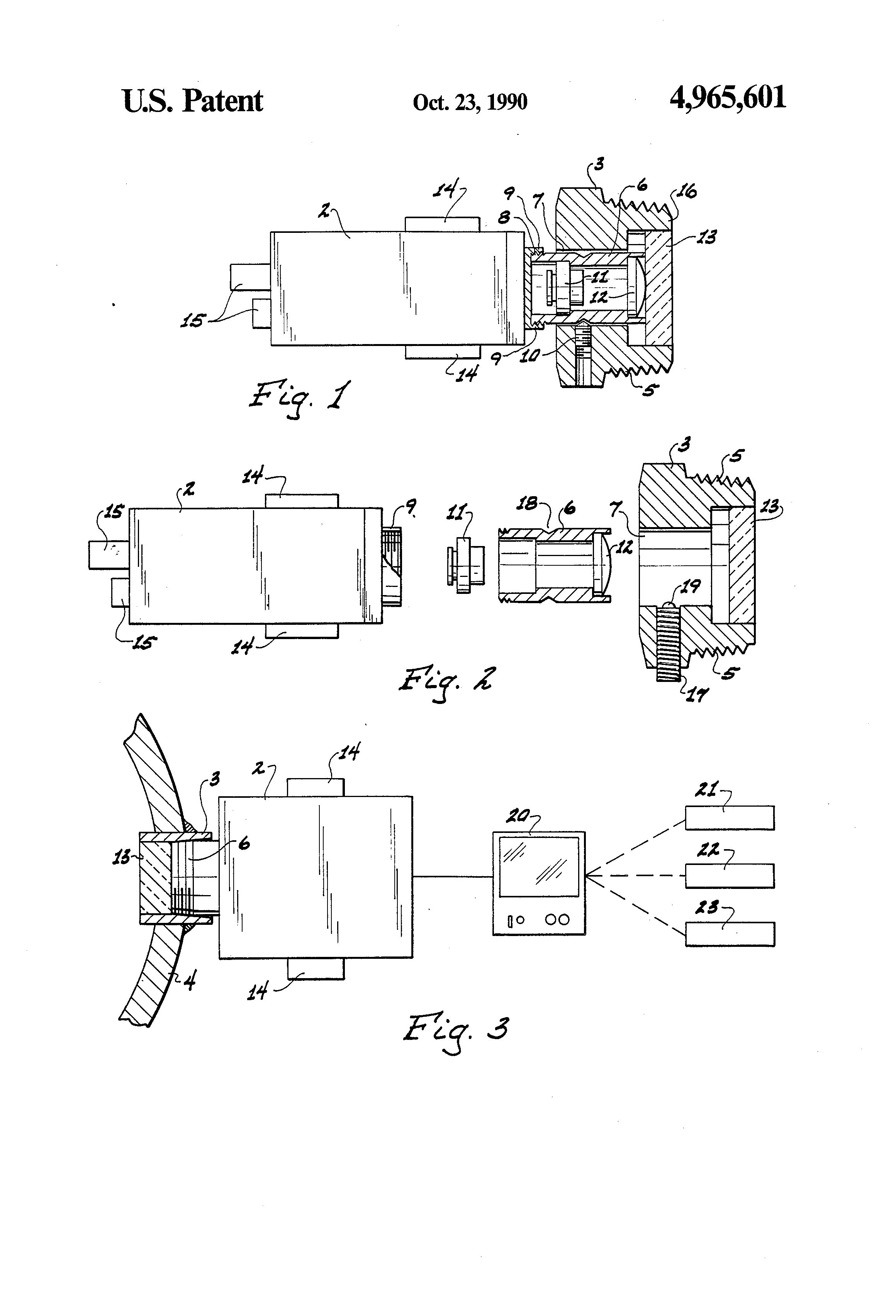
A camera viewing unit for viewing the inside of a reaction vessel or the like is the invention disclosed. This viewing unit has a fixed lens positioned in front of the camera lens. The camera is focused by moving the fixed lens. The camera has a fused lens in front of the fixed lens; this fused lens minimizes corrosion of the unit. There are also easy alignment means to ensure a level picture is transmitted.
CAMERA
VIEWING
UNIT
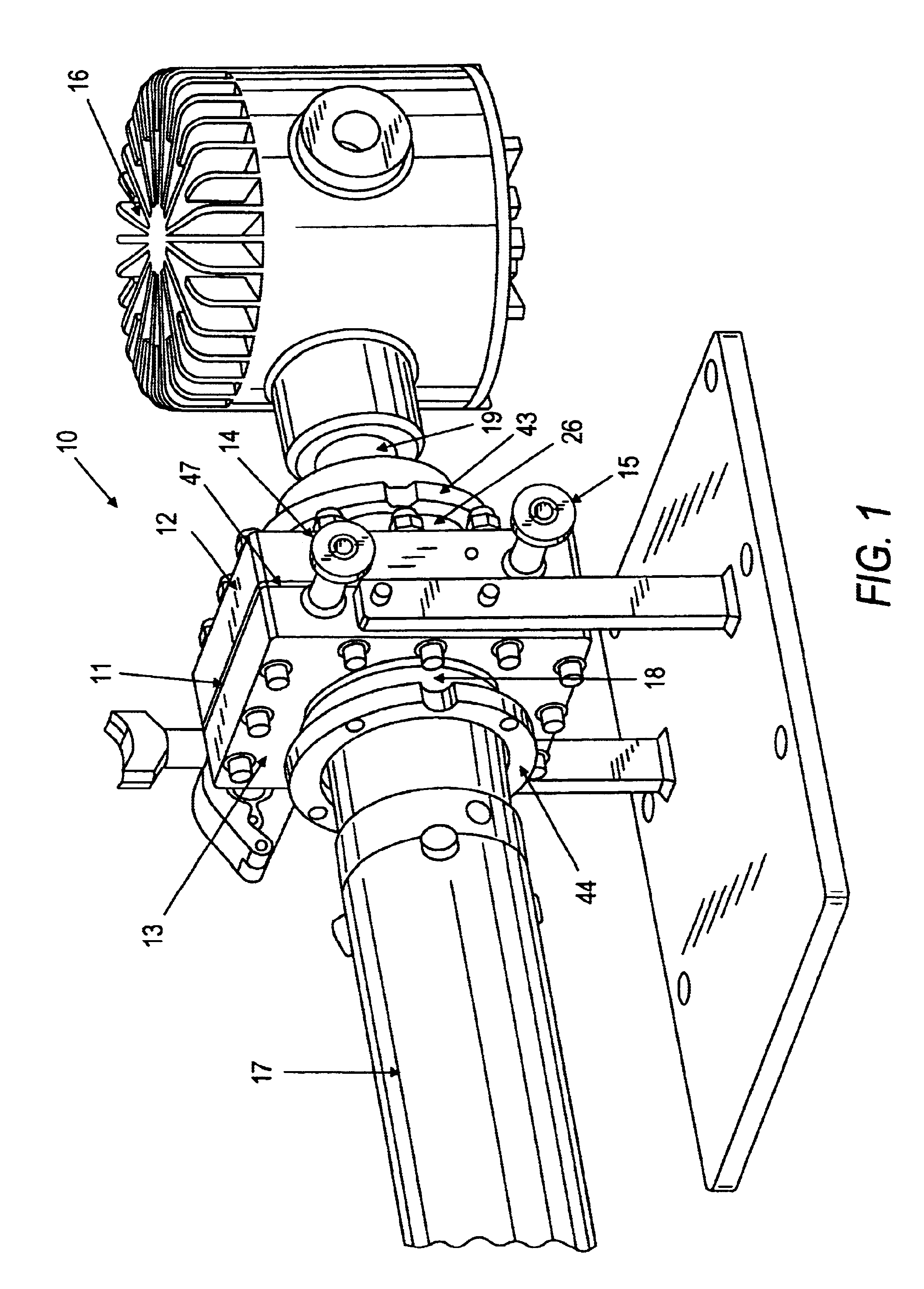
A camera viewing unit for use in viewing the interior of a high pressure vessel that has a CCTV camera spring mounted within a hermetically-sealed housing. The camera can be focused from outside the housing by a structure which moves the camera horizontally while the lens remains stationary. By moving the camera toward and away from the object to be viewed, the camera can be focused by the user at a location remote from the pressurized vessel. There is also a plate connected to the camera which can be rotated to thereby align the camera to ensure that a level image is obtained.
QUICKPORT
CLOSURE
DEVICE
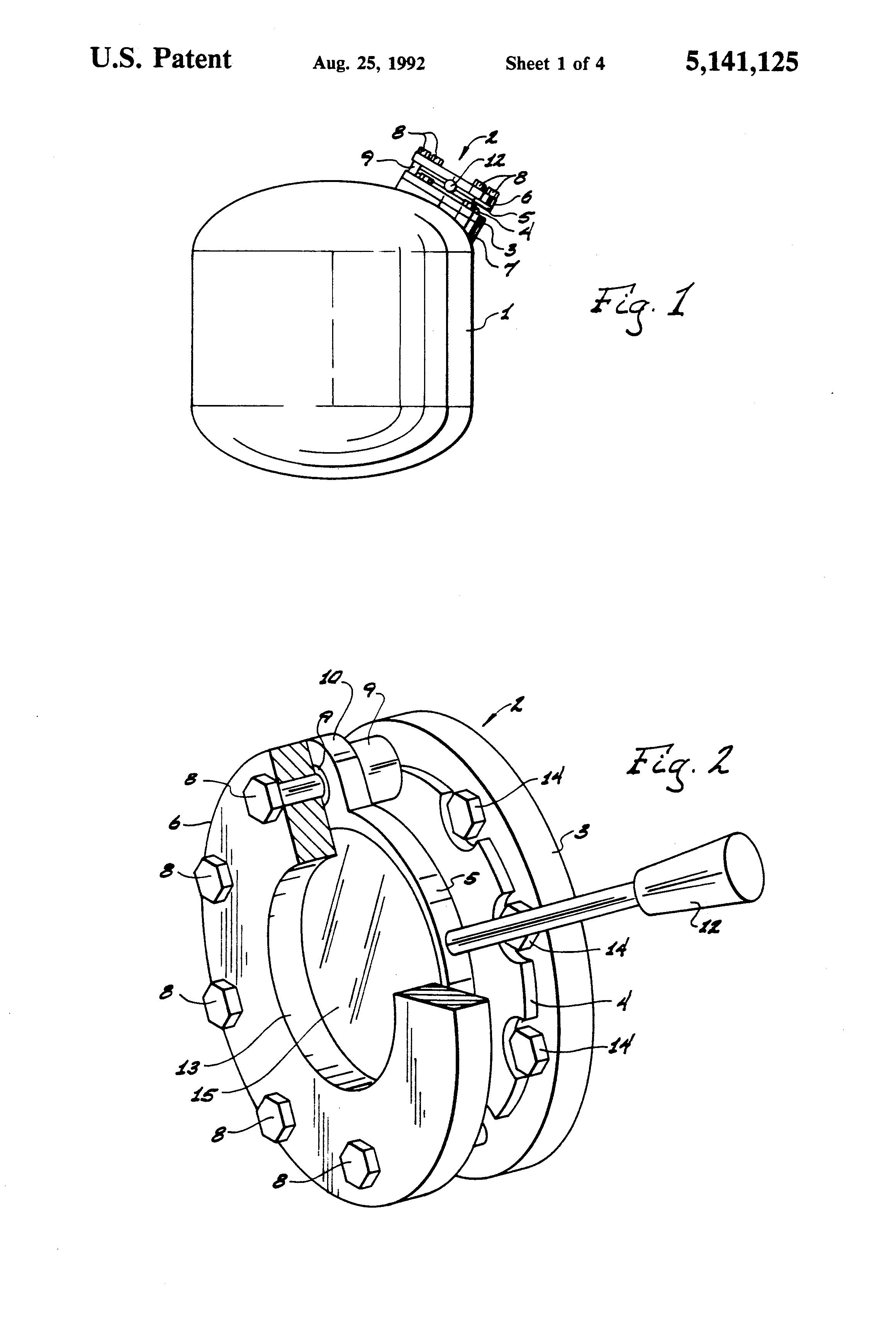
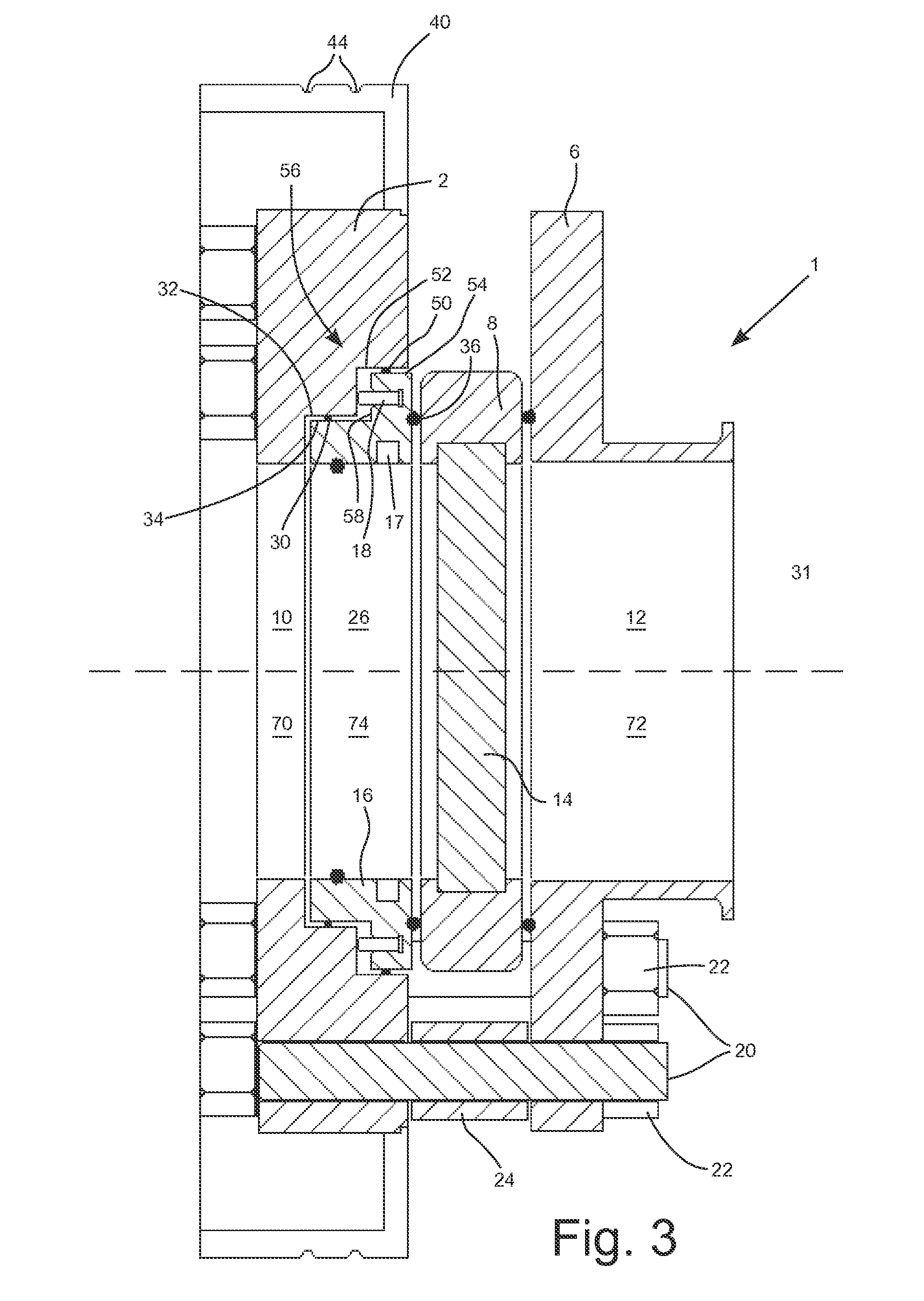
In using various vessels such as reaction vessels there must be provisions for adding materials to the vessels and for observing the vessel contents. The structure of this invention provides a vessel closure device that provides both of these conveniences. This closure device has an annular seal ring containing spring plungers each located outside areas of exposure to the contamination of the vessel. The seal ring also has two O-ring seals to ensure against leakage. There is also provided a sliding door with a viewing window that is aligned with all openings in the other closure device components in order to provide a clear viewing and addition path to the interior of the vessel.
LIGHTING
AND
VIEWING UNIT
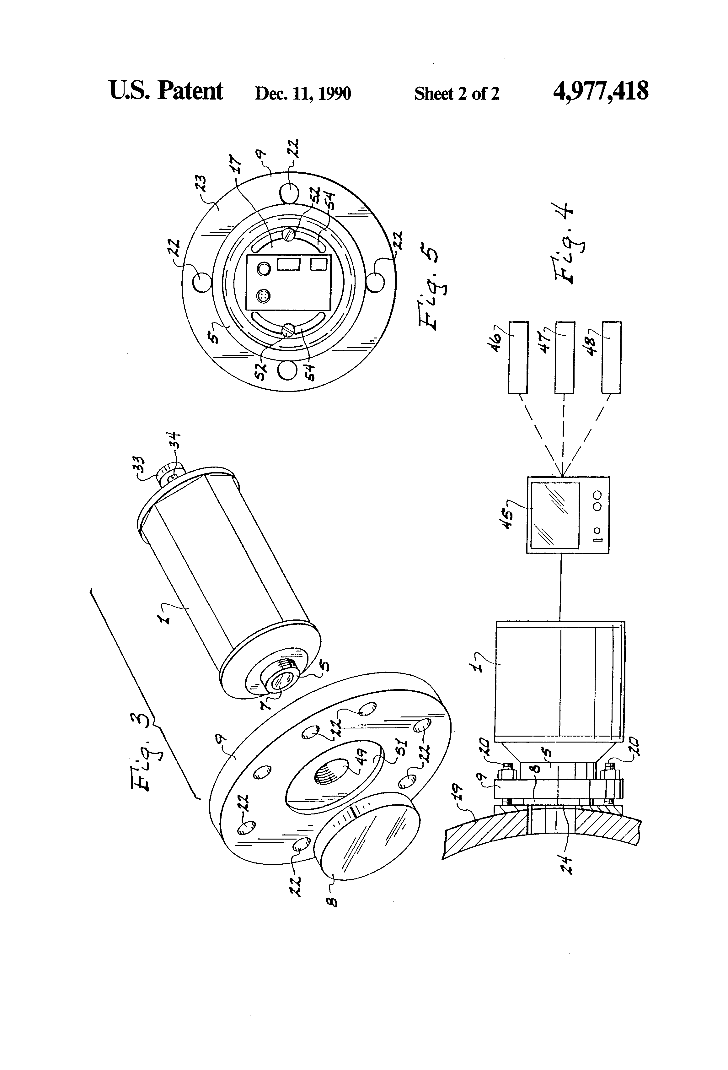
A unit for viewing and supplying light or radiant energy to the interior of a vessel that has a front fused glass window. The light and camera-viewing means see the interior of a vessel through this fused glass window which provides a substantially corrosion-proof seal across the entire distal portion of the unit. The light and camera-viewing means are pointed into the interior of the vessel in substantially the same direction.
WELDABLE
SIGHTGLASS
ASSEMBLY
The invention provides a sightglass assembly for viewing the interior of a vessel, such as a reaction vessel for chemical or biochemical reactions, and is adapted to be welded to a vessel wall. The sightglass assembly comprises a window disc fused to a metal frame having a flange extending radially therefrom. The assembly is set into an appropriately sized opening in the vessel wall and the outer perimeter of the flange is welded to the vessel wall. An annular groove in the flange, surrounding the frame and window disc, absorbs stresses created by the heat of welding and thus protects the integrity of the entire unit. When installed, the sightglass assembly and inner face of the tank wall provide an easily cleanable smooth continuous surface, free of recesses and crevasses where bacteria can collect and grow or product from previous batches can accumulate and cause contamination.
MULTI-PORT ILLUMINATING
AND
VIEWING UNIT
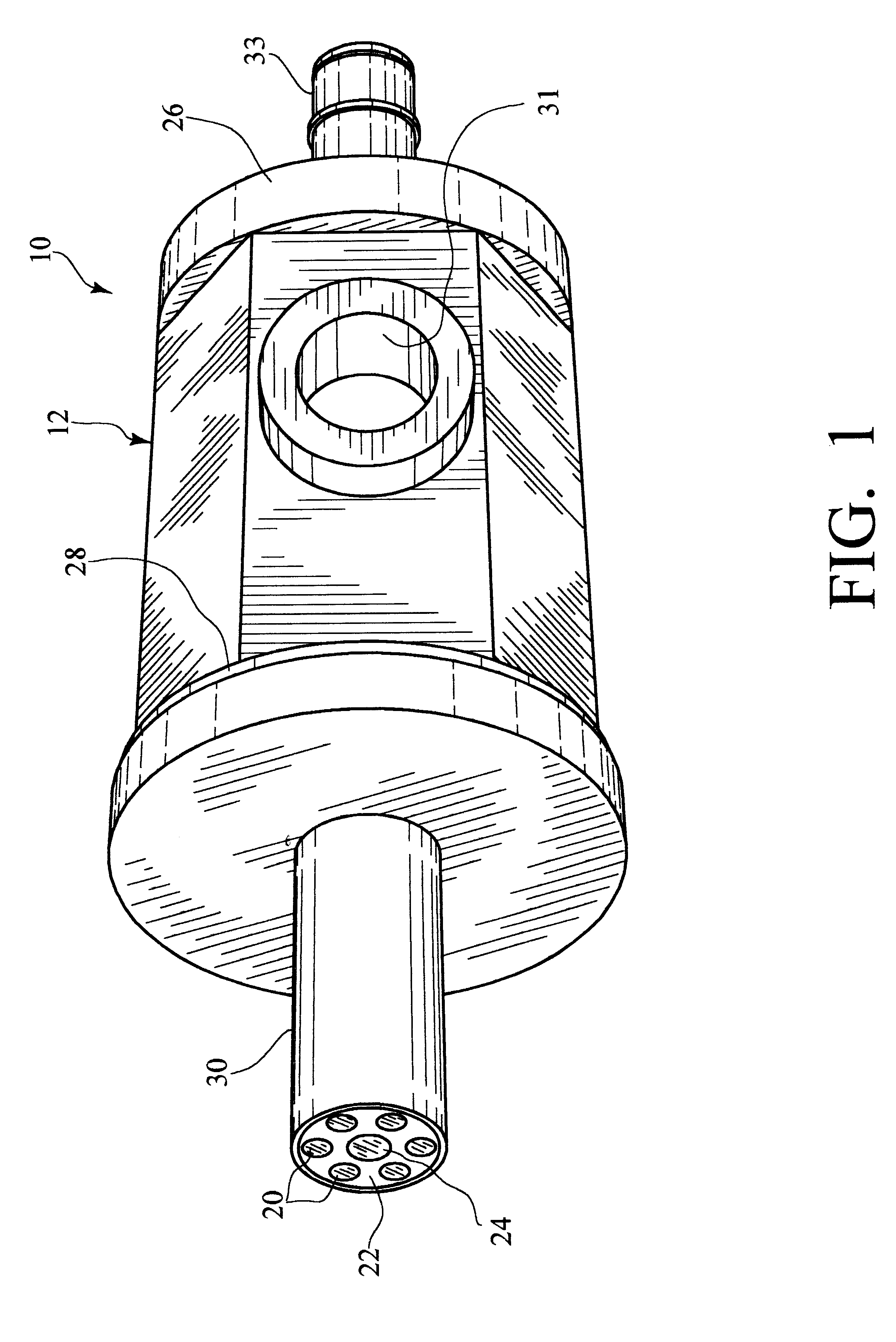
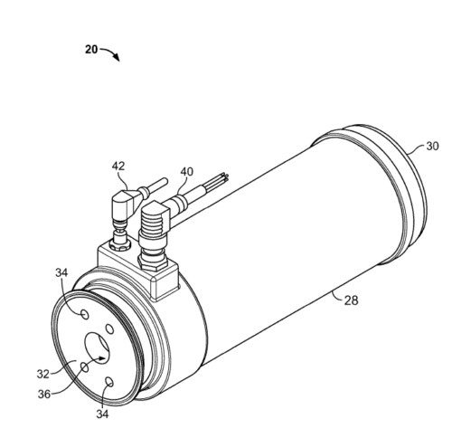
An illuminating and viewing unit for illuminating the interior of a vessel with source radiation and observing the vessel interior comprises a housing including a front wall facing the vessel interior. The front wall is of a material that does not transmit the source radiation, and includes one or more illumination ports individually fused into the front wall that transmit the source radiation to the vessel interior. A detection port is also individually fused into the front wall for transmitting detectable radiation along a detection path from the vessel interior to a radiation detector mounted in the housing. The optical isolation of the illumination and detection ports in the front wall prevents unwanted internal reflection of source radiation into the detection path, and allows for independent selection of port materials and configurations, while maintaining a hermetic seal between the housing and the internal contents of the vessel.
FLUID
FLOW
CELL
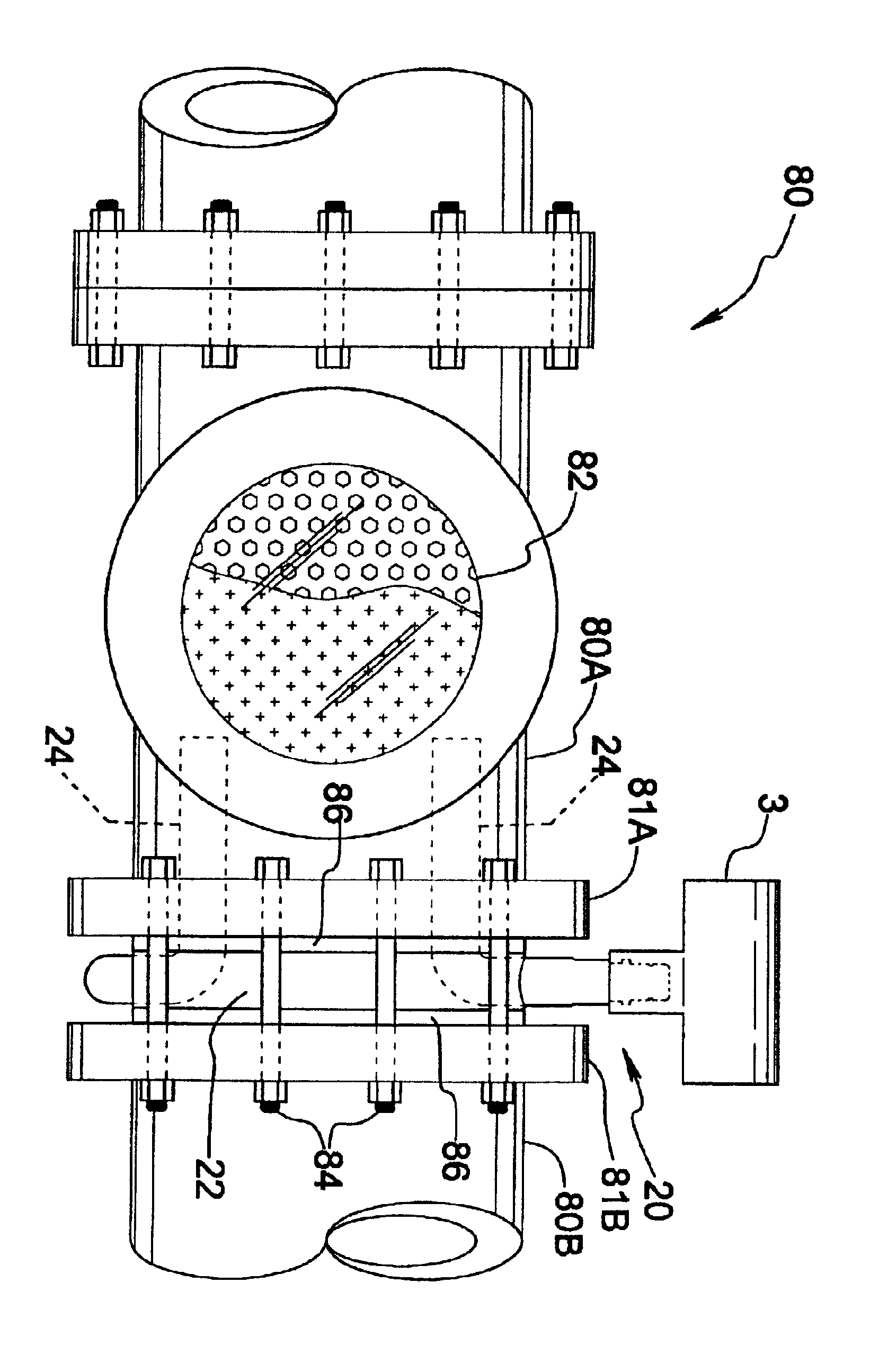
A flow cell device for observing a fluid including a housing defining an inlet and an outlet and a viewing assembly coupled to the housing. The viewing assembly includes a first viewing member disposed adjacent to an aperture in fluid communication with the inlet and the outlet. The first viewing member is configured to enable a viewing of the fluid in the aperture and is adjustable with respect to the housing so that a thickness of the aperture is variable. In addition, a method for observing a fluid in a flow cell includes passing the fluid through an adjustable aperture that is defined on a first side by a first viewing member that is moveable so that a thickness of the apeture is adjustable. The method also includes viewing the fluid through the first viewing member as the fluid passes through the aperture.
MODULAR INSERTION DEVICE
FOR PROCESS ILLUMINATION
AND VIEWING
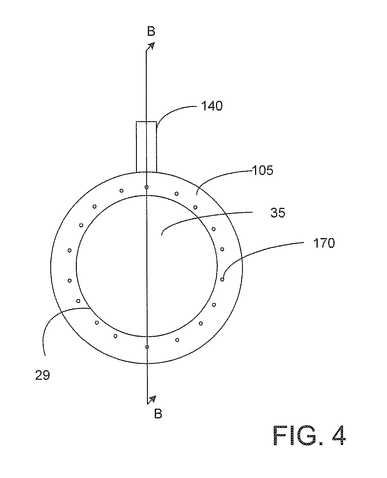
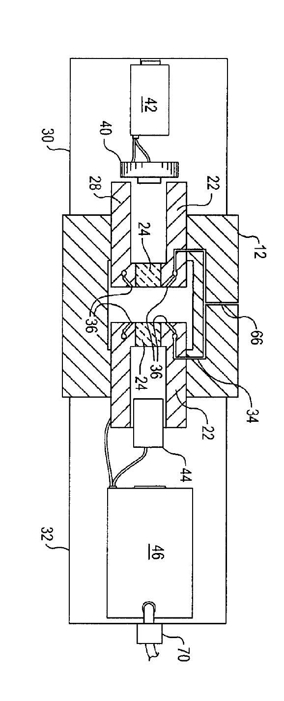
An illumination module comprises a ring-shaped mounting member having an axially extending viewing passage and an L-shaped radiation guide including a radiation entry end for communication with an external radiation source and a radiation exit end provided with a fused glass window for insertion within a process vessel or pipeline. The radiation guide extends through a radial guide hole in the mounting member and bends to run axially along the passage of the mounting member in close proximity to the wall of the passage so as to minimize blockage of available viewing area through the passage. The illumination module can be clamped between a sight glass or camera viewing unit and the flange of a nozzle port, or between segments of a pipeline near a viewing window of the pipeline, to form an illumination and viewing assembly. A coarse flow duct system in the mounting member, and a fine flow duct system in the mounting member and radiation guide, enable delivery of cleaning fluid to a sight glass or camera unit, and to the fused glass window of the radiation guide, respectively.
GRANULAR PRODUCT
INSPECTION
DEVICE
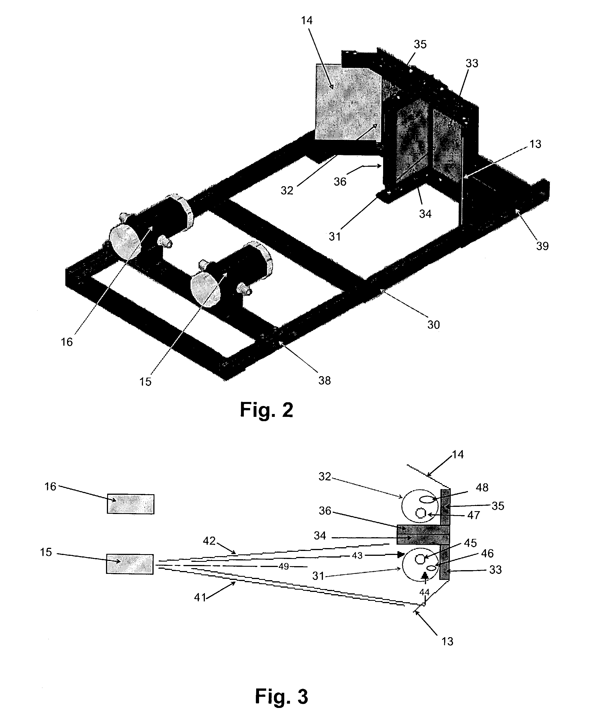
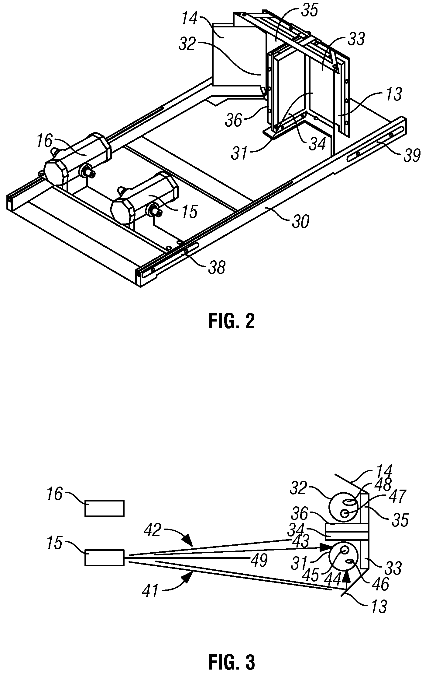
A particle inspection device includes a feeder configured to drop a particle through an image area, a reflector configured to provide a reflected view of the particle in the image area, and an image capturing device configured to capture an image of the particle in the image area such that the image includes at least a direct view of the particle and the reflected view of the particle. In addition, a method for inspecting a particle includes dropping the particle through an image area, providing a reflected view of the particle in the image area using a reflector, and capturing an image of the particle in the image area using an image capturing device so that the image includes a direct view of the particle and the reflected view of the particle.
INSERTION FLUID
INSPECTION
DEVICE
A fluid inspection device for inspecting a fluid in a vessel includes an elongate insertion well having a rear end disposed at the wall of the vessel and a front end disposed in the interior of the vessel. An inside of the insertion well is sealed off from the fluid in the vessel and an outside of the insertion well is in contact with the fluid in the vessel. A camera unit is disposed in the inside of the insertion well, and a lens in operative communication with the camera unit is disposed at the front end of the insertion well so that a front end of the lens is in contact with the fluid and a rear end of the lens is inside the insertion well. In addition, a light guide having a light emitting end is configured to guide light from the inside of the insertion well to the light emitting end. The light emitting end is disposed forward of the front end of the lens and directs the light at an angle toward the front end of the lens, and a gap between the front end of the lens and the light emitting end is capable of receiving the fluid.
GRANULAR PRODUCT
INSPECTION
DEVICE
A particle inspection device includes a feeder configured to drop a particle through an image area. The feeder includes a tray surface having a flat portion and an edge portion disposed above the image area. The inspection device also includes a vibration device configured to vibrate the feeder induce movement of the particle from the flat portion to the edge portion and an image capturing device configured to capture an image of the particle in the image area. The edge portion may be a downwardly curved edge section and configured to maintain the orientation and reduce tumbling motion as the particle slides off the tray and falls through the image area. Alternately or additionally, a landing element is provided having a landing surface disposed in the image area and angled with respect to the flat portion of the tray surface and configured to receive the particle. The image capturing device is configured to capture an image of the particle on the landing surface.
GRANULAR PRODUCT
INSPECTION
DEVICE
An inspection device for inspecting a granular product includes a feed tray having a receiving region for receiving the granular product and an imaging region and a vibration device configured to impart vibrations to the feed tray for moving granules of the granular product from the receiving region to the imaging region. The inspection device also includes an image capturing device configured to capture an image of a sample of the granular product in an image area of the imaging region. In addition, a method for inspecting a granular product includes disposing the granular product on a receiving region of a feed tray, vibrating the feed tray so as to induce a movement of the granular product from the receiving region of the feed tray to an imaging region of the feed tray, and capturing an image of a sample of the granular product in an image area of the imaging region.
FLOW CELL
SPRAY
RING
A flow cell device for observing a fluid includes a housing defining an inlet and an outlet, a first viewing member, and a second viewing member. The first viewing member, which is disposed in and coupled to the housing, includes a first window and a spray ring. The spray ring includes cleaning ports in fluid communication with a cleaning fluid inlet port. The second viewing member includes a second window and is disposed in and coupled to the housing opposite the first viewing member such that an aperture that is in fluid communication with the inlet and the outlet is defined between the first window and the second window. The spray ring does not extend past a surface of the first window facing the aperture and each of the cleaning ports is oriented such that a fluid provided under pressure to the cleaning ports is ejected toward the second window.
VESSEL PORT CONFIGURED
FOR USE WITH A
GLOVE BAG
A port and closure device for a vessel that is configured for use with a glove bag. The port comprising includes a first annular flange with an opening, a second annular flange disposed a predetermined distance from the first flange and also having an opening, and a seal ring disposed adjacent the first annular flange and having an additional opening. At least a portion of the openings are aligned so that a path is provided through the flanges and the seal ring. A slideable door is included in the port between the seal ring and the second annular flange. The slideable door has a first position that obstructs the path and a second position that is outside of the path. Springs are disposed between the first flange and the seal ring that urge the seal ring toward the slideable door. To reduce contamination sites, the springs may be sealed within an annular interface between the first annular flange and the seal ring. Alternatively, or in addition, a funnel pipe may be used with the port disposed in the openings of the first and second flange and the seal ring. The port may also include an adapter configured to hold a glove bag thereon.
DIRECT LINE SAMPLING
DILUTION SYSTEM
A direct line sampling system includes a flow line for a process flow, a diluent flush line for a diluent, and a sampling valve structure disposed in the flow line. The sampling valve structure includes a sampling chamber and has a first position in which the sampling chamber is in communication with the flow line so as to provide a path for the process flow through the sampling chamber. The sampling chamber captures a sample from the process flow when the sampling valve structure switches to a second position in which the sampling chamber is in communication with the diluent flush line. The diluent flushes the sample to a mixing chamber disposed downstream of the diluent flush line where the sample is diluted. An outlet line extends from an outlet of the mixing chamber to an analysis instrument configured to analyze particles in the diluted sample of the process flow.
FLOW ANALYZER FOR
HARSH ENVIRONMENTS
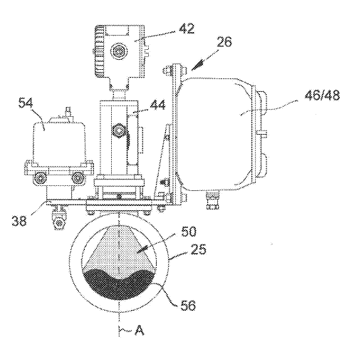
A flow analyzer includes a flow body having a single-piece construction. The flow body includes a flow path extending through the flow body along a flow direction between opposing inlet and outlet ports and an enclosed wiring conduit extending substantially transverse to the flow direction between a first side of the flow body and a second side of the flow body. The enclosed wiring conduit is isolated from the flow path. An illumination unit is disposed on the first side of the flow body and configured to illuminate fluid within the flow path. An observation unit is disposed on the second side of the flow body and configured to visually observe the fluid within the flow path.
FOAM LIQUID
MONITORING SYSTEM
A monitoring system for monitoring a process includes a housing with a viewing panel. The viewing panel includes a view port. An emitter generates light and illuminates an observation zone of the process. A detector is disposed within the housing and is configured to detect light entering the housing through the view port and create a plurality of images of the process in the observation zone. A thermal regulation system is configured to generate heat in the vicinity of the viewing panel of the housing so as to increase the temperature of at least the view port above ambient temperature.
MUD FLOW MONITORING
DEVICES AND METHODS
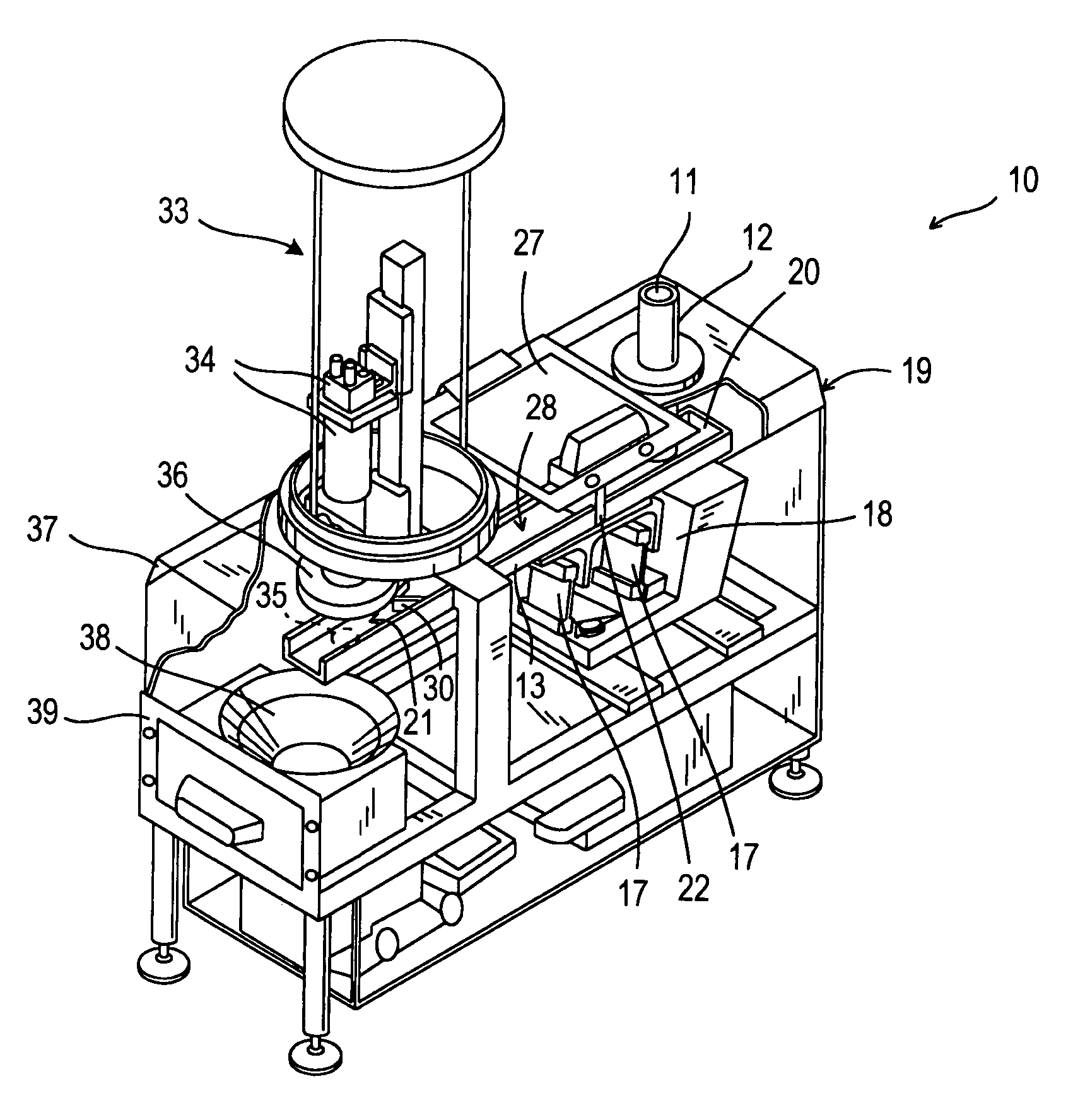
A flow monitoring device for monitoring mud flow in a return line of a bore hole drilling operation, including a mounting bracket mounted to the return line with a viewing port for access to an interior of the return line. A light source illuminates, through the viewing port, a portion of the mud flow in an observation zone within the return line. A camera creates a plurality of images of the mud flow in the observation zone. A controller is configured to analyze the plurality images to: determine a level of the mud flow in the return line and the presence of at least one irregularity, track a movement of the irregularity across the plurality of images to determine a rate of movement of the irregularity, and calculate a flow rate of the mud flow through the return line based on the movement rate and the determined level.
Latest Posts
 11 November 2024 by Colleen Dressel, in Latest posts,Tech
NIBRT & JM Canty
NIBRT and JM Canty win Pharma Project of the Year at the Pharma Industry Awards ...READ MORE + 15 September 2022 by Colleen Dressel, in Latest posts,Tech
NIBRT announce a second phase of collaboration with JM Canty
This photo was taken during a recent visit by Canty to NIBRT. From left to right...READ MORE + 29 June 2017 by Tod Canty, in Uncategorized
ASTM D02 Award
Tod Canty receives award from ASTM D02 CS96 committee in appreciation of work to...READ MORE +
Particle Sizing
Have a need for particle sizing for the Lab and Online? Fill out our Particle Sizing Questionnaire and learn more about our particle sizing systems.
Take the Questionnaire now!
Go Green Projects
Include applications for Oil in Water monitoring for the petroleum industry to make sure discharges are within drinking water limits. Particle size and shape knowledge is critical in maintaining and improving these processes.
Find out more
Historical Accomplishments
NASA's replacement of all sight glasses in the shuttle launch pad fuel lines with Fuseview™ sight glasses. The constant leakage failure prior to Fuseview ™ sight glasses was the number one source of delays.
Find out more

